Power Supply Pcb Diagram
Each of the schematic is very simple to construct and will function without problems if you respect the maximum power supply ratings. For clarity, the parts responsible for miscellaneous auxiliary functions, such as current limit, fan control, and ov.
12V 3A Power Supply Circuit Using 2N3055 Transistor

Power supply and power control circuit diagrams / circuit schematics note that all these links are external and we cannot provide support on the circuits or offer any guarantees to their accuracy.

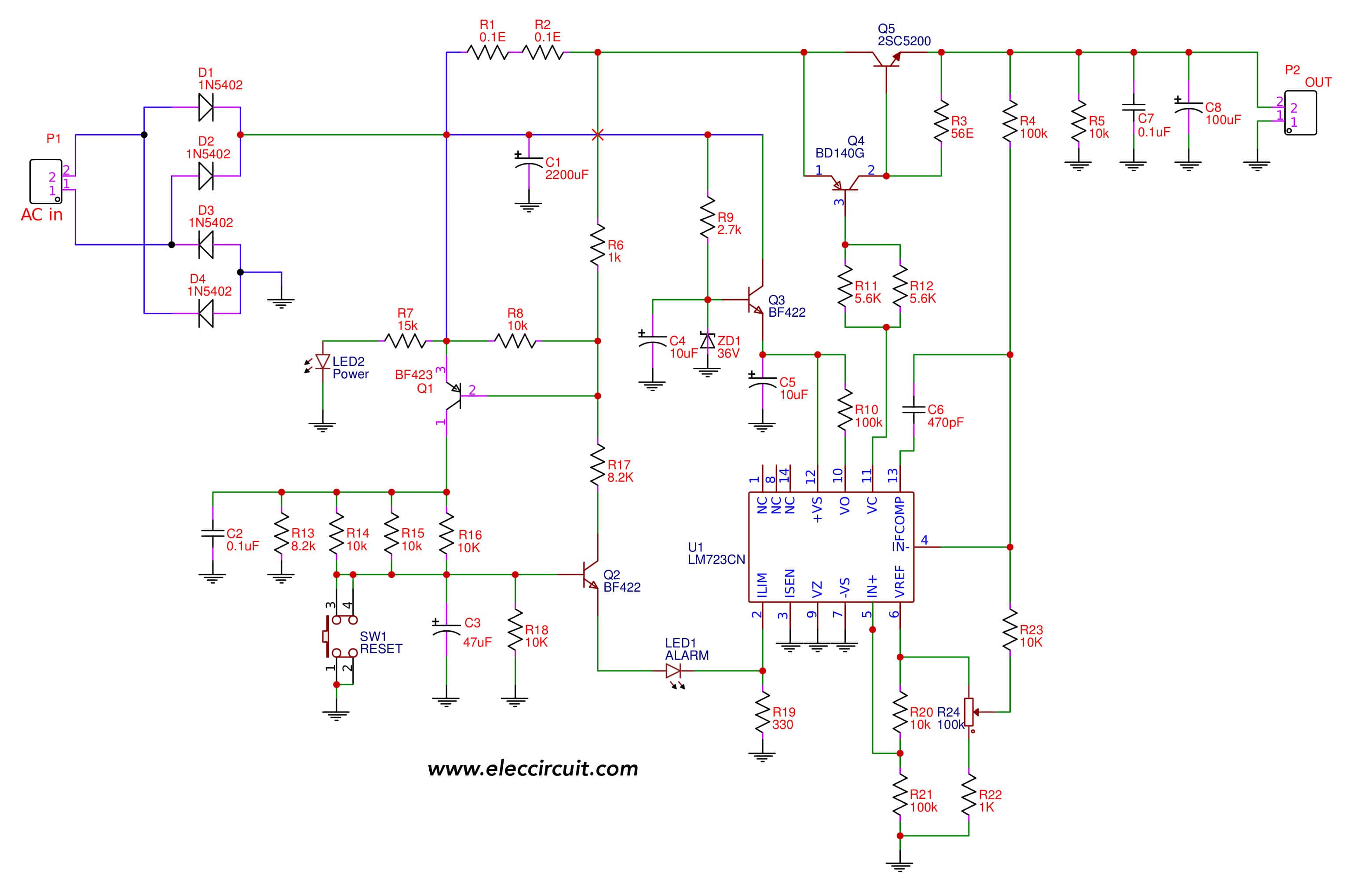
Power supply pcb diagram. We've seen a number of power supply circuits up to this point, but the key advantage of this one is that it can alter the output voltage and current. The regulated power supply is based on 2 lm723 (uc723), normally lm723 can control current and voltage by itself. Variable supply that can be varied from 1.2v to 30v at a current of 1 amphere.
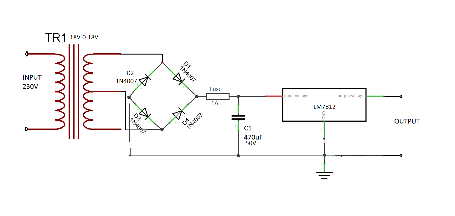
Warning if you are considering building or repairing a power supply, especially one that is powered from mains (line) voltages the power supply modules on this site will help you understand how many commonly encountered circuits work. A transformer, a diode and a capacitor.the transformer is the device which has two sets of windings, one primary and the other one is the secondary. First power supply circuit is built with bd139, one zener diode and a few passive components.
It changes in most cases reduces the level of supply to a value suitable for driving the load circuit. I have built many circuits in my life, but this is actually the first time i've built a power supply circuit from scratch. Load − the load which uses the pure dc output from the regulated output.
The block diagram of a regulated power. Regulated power supply is an electronic circuit that is designed to provide a constant dc voltage of predetermined value across load terminals irrespective of ac mains fluctuations or load variations. The top right and bottom right part is the header pins.
The voltages offered are ac voltages measured in volts rms. The switch mode power supply circuit with very low output power of less than 100w (watts) is commonly a type of fly back converter smps & it is very simple & low cost circuit compared to other smps circuits. In order to easily understand the circuit, it is segmented into four parts.
This is a 5v 12v switching mode supply circuit15a max. A regulated power supply essentially consists of an ordinary power supply and a voltage regulating. In this final section on pcb layout, we're going to look at reduced schematics from the.
It is an old schematic of 200w pc power supply. Motorola offers a wide range of power supervisory circuits that fulfill these needs in a cost effective and efficient manner. 12v bd139 power supply circuit
For security, the fuse needs to be set the live wire path to the transformer. And it requires only 5 components. Some circuits would be illegal to operate in most countries and others are dangerous to construct and should not be attempted by the inexperienced.
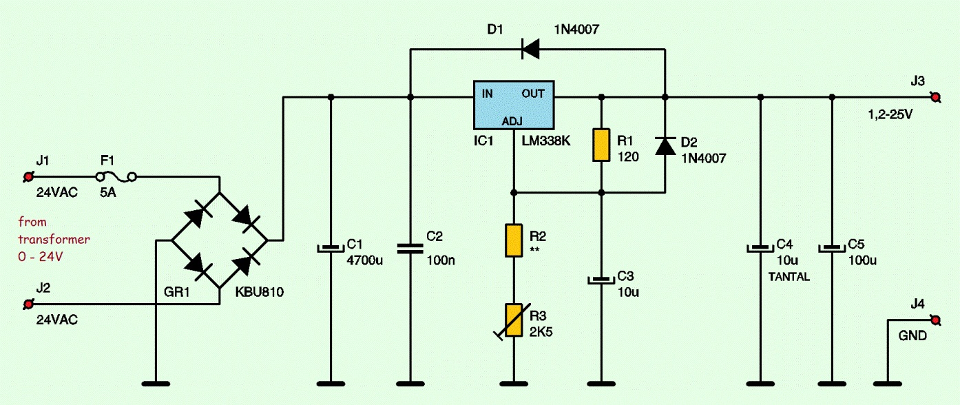
It can be adjusted for currents from 100ma up to 4.3a. It has three distinct portions, the power transformer, the full wave bridge rectifier and the filter capacitor. This is a conceptual circuit diagram of the power train of a typical atx computer power supply unit.
Lm741 opamp is used for ac voltage stabilization. A single rail power supply is displayed in the diagram below. Regulator − a voltage regulator circuit in order to control the voltage to a desired output level.
This schematic does not show the control circuitry, that's why you see all mosfet gates and transistor bases are open. The fuse is installed in the live wire path to the transformer for safety. Adjustable output voltage from 0v to 30v.
The final project i wanted to build was a wall adapter with a usb socket to charge my iphone. The circuit was created using easy eda. The diagram below shows a partial schematic of a 450 watt atx power supply.
The power supplies are the mainstay of electronic circuits. Mains 220v or 120v is fed to the primary winding which is transferred to the. The complete circuit diagram for this breadboard power supply project is shown below.
Block diagram of a power supply unit. In this design, separate lm723 is used for voltage and current part. A basic power supply circuit will fundamentally require three main components for providing the intended results.
The circuit of a 15 v dual power supply is shown above. Figure 1 above shows the circuit diagram of the laboratory power supply. This is adjustable elctronic fuse that can be used to protect power supplies from short circuits or can be also used to limit the current usage.
The top left and bottom left part is the 5v regulator and 3.3v regulator respectively. This power supply circuit is easy to build and cheap. Smoothing − a filtering circuit to smoothen the variations present in the rectified output.
12v dc power supply schematics. Modern power supplies, the study of which is essential to an understanding of electronic systems.

030 VOLT 010 AMPS ADJUSTABLE SHIELDED POWER SUPPLY

Simple Variable power supply circuit 030V 2A
Complete Circuit Diagram of ±035Volts Dual Regulated DC
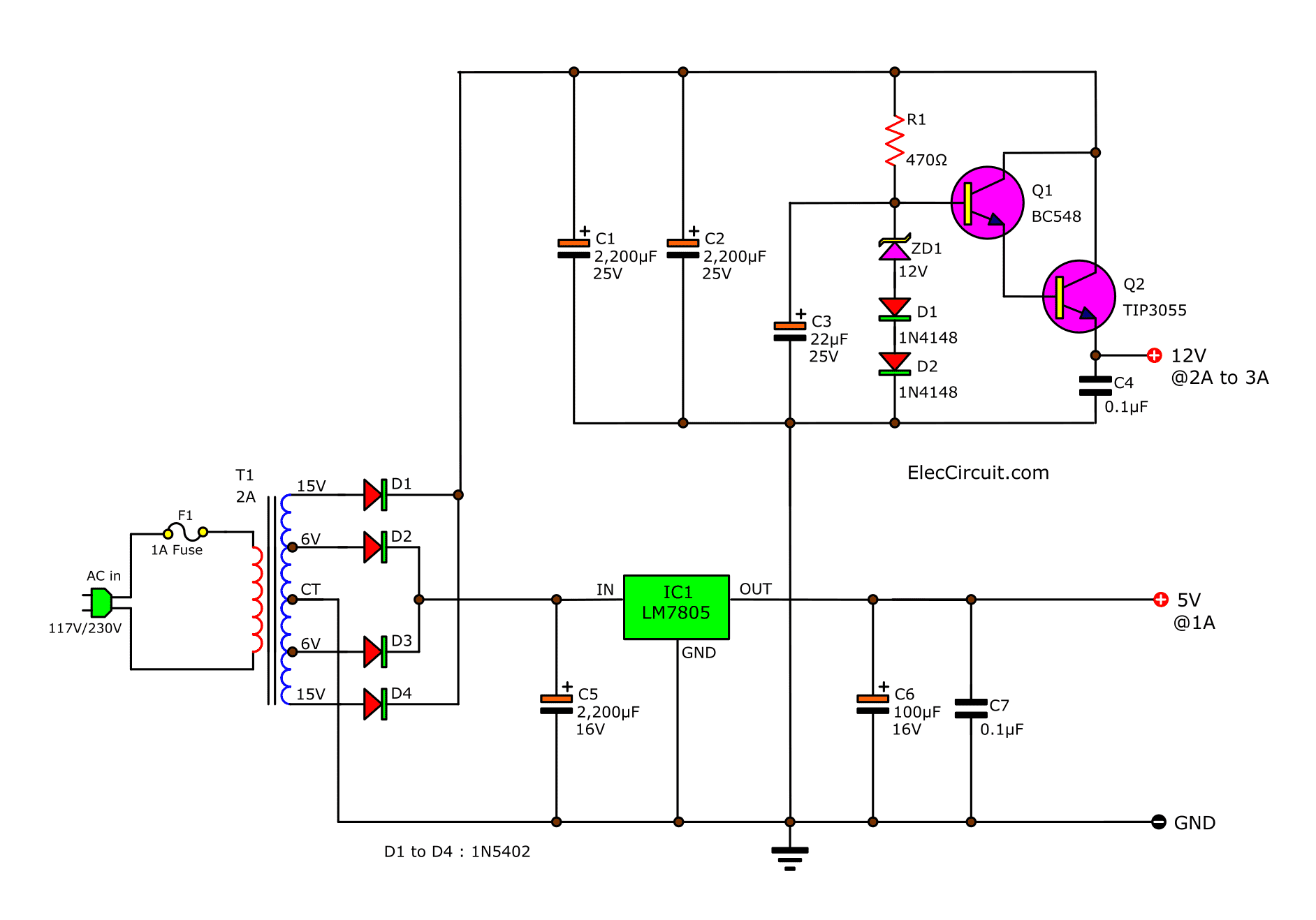
Many ideas of 12V and 5V Dual Power Supply Circuit Diagram

Simple 050V 2A Bench Power Supply Circuit Diagram

Dual Adjustable DC Power Supply

0 to 50V, 0 to 10amp Variable Dual Power Supply Power

12 Volt 10 Ampere DC Power Supply Circuit
Variable power supply circuit, 050v at 3A with PCB
Constant 12V Power Supply for LED Circuits (Part 4/13)
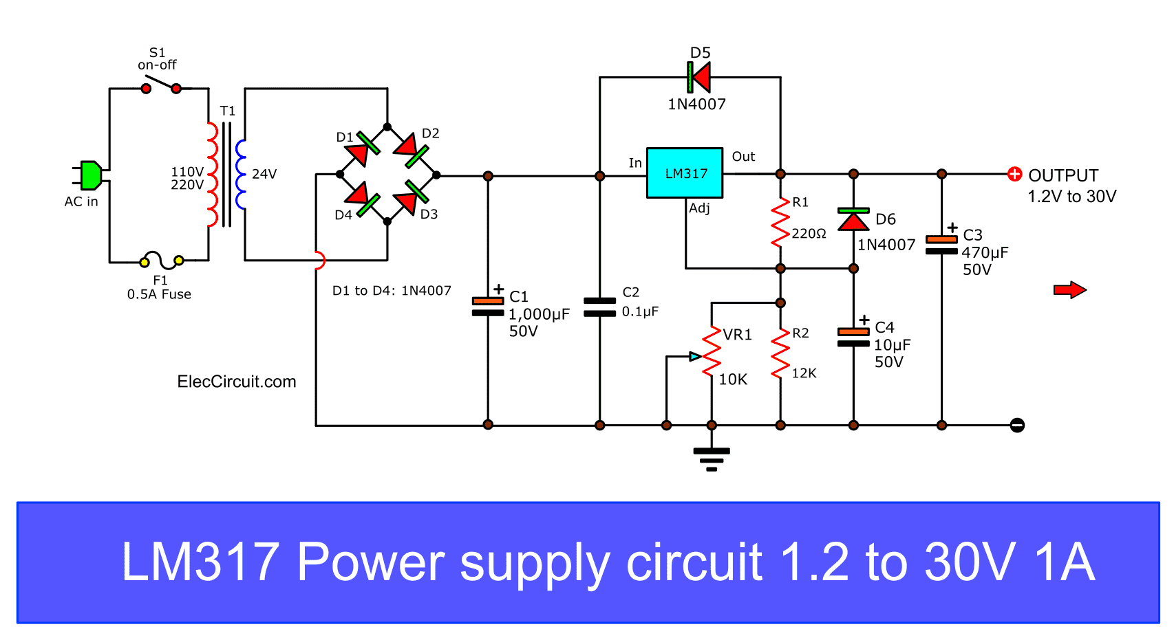
My first variable power supply using LM317 ElecCircuit
Variable / Adjustable DC Power Supply 1.2V 25V using

24 Volt 5 Ampere Power Supply Circuit
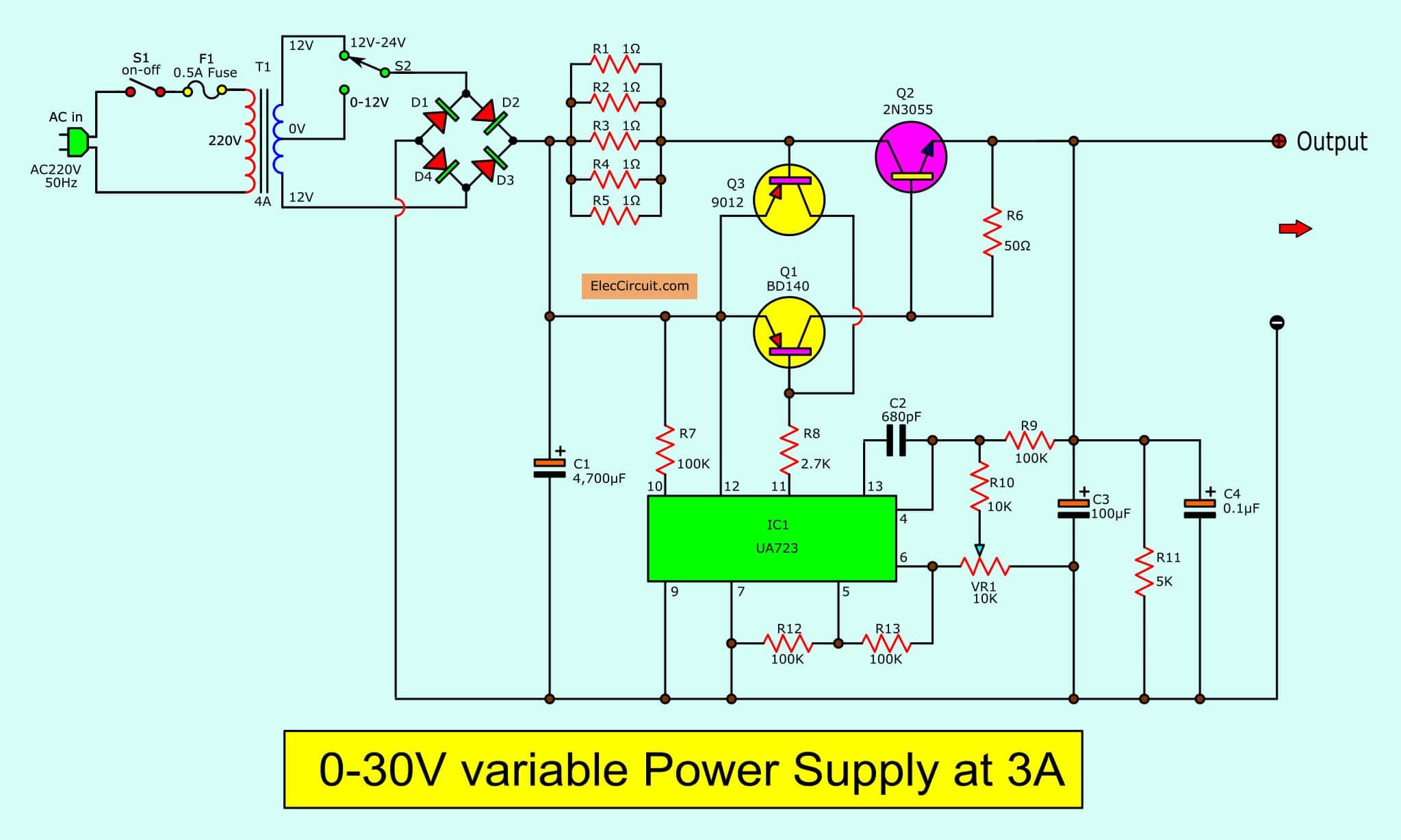
030V Variable Power Supply circuit Diagram at 3A
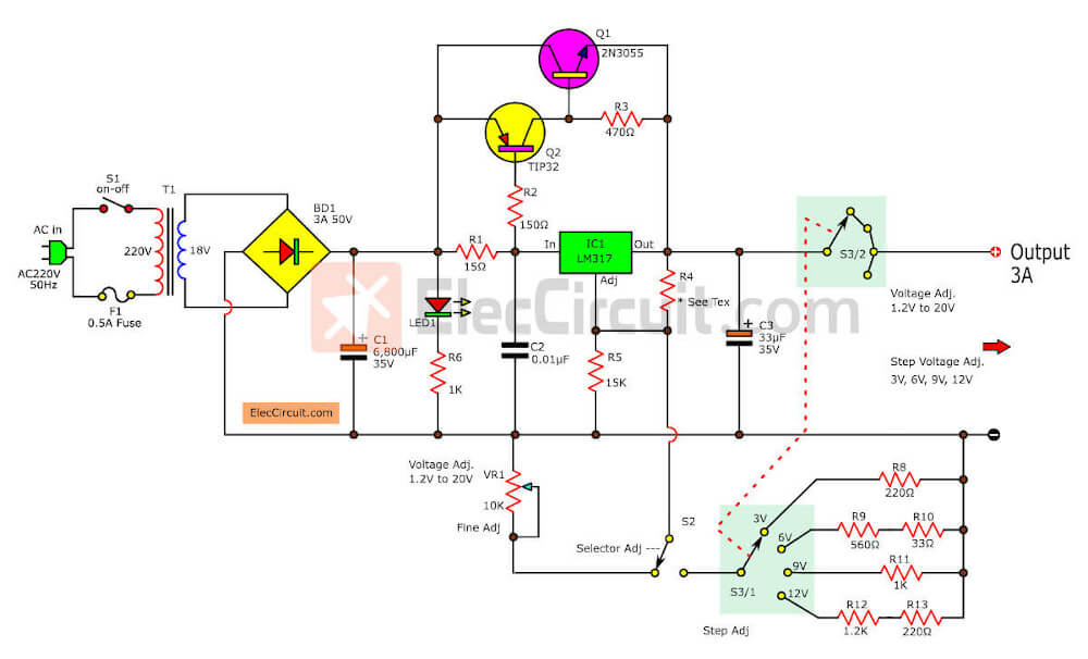
LM317 2N3055 3A Variable power supply

12V 1A SMPS Power Supply Circuit Design on PCB Power
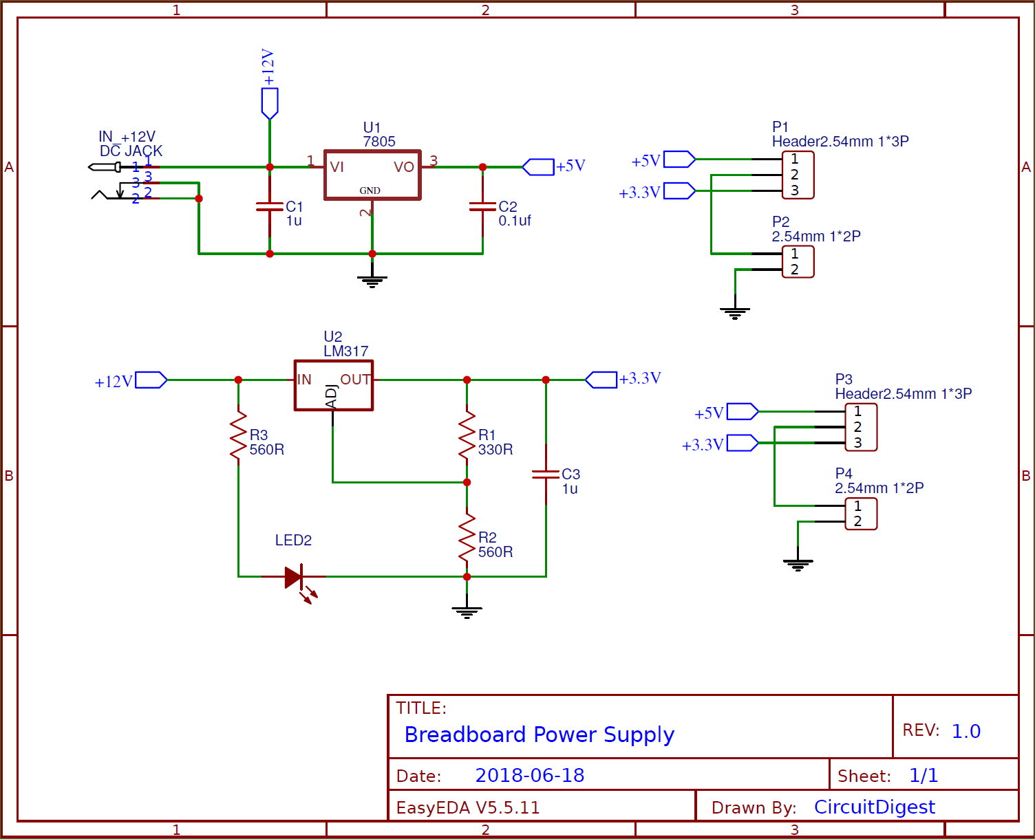
DIY Breadboard Power Supply Circuit on PCB
9 ways to build 24V power supply circuits with easy parts

5V Power Supply Circuit